How do big pneumatic actuator butterfly valve minimize pressure drops in large-diameter pipelines?

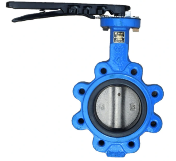
Big pneumatic actuator butterfly valves are specifically designed to minimize pressure drops in large-diameter pipelines by leveraging their unique characteristics and design features.

Here’s how they achieve this:

  1. Streamlined Flow Path: Big pneumatic actuator butterfly valves are designed with a streamlined flow path through the valve body and disc. The disc, when fully open, creates a smooth, unobstructed flow path, minimizing turbulence and reducing pressure drops across the valve. This streamlined design allows fluids to flow through the valve with minimal resistance, optimizing flow efficiency and reducing energy consumption.
  2. Low Friction Seal: The sealing mechanism of big pneumatic actuator butterfly valves is designed to minimize friction and resistance to flow. Resilient seat materials, such as EPDM or PTFE, are used to create a tight seal between the disc and the valve body while maintaining low friction characteristics. This ensures that the valve provides effective shut-off without impeding flow when fully open, minimizing pressure drops across the valve.
  3. Large Flow Capacity: Big pneumatic actuator butterfly valves are specifically designed to handle large flow rates commonly encountered in large-diameter pipelines. The disc geometry and size are optimized to maximize flow capacity while minimizing flow restrictions and pressure drops. This allows the valve to efficiently regulate flow in high-flow applications without causing significant pressure losses.
  4. Compact Design: Despite their large size, big pneumatic actuator butterfly valves are designed to be compact and lightweight compared to other types of valves, such as gate valves or globe valves. The compact design minimizes the space required for valve installation and reduces the overall weight of the valve assembly. This not only simplifies installation but also reduces the structural load on the pipeline, minimizing pressure losses due to pipe deflection or bending.
  5. Quick Response Time: Pneumatic actuators used in big butterfly valves offer quick response times, allowing for rapid valve opening and closing in response to changes in flow conditions or control signals. This quick response capability minimizes flow disturbances and pressure surges associated with valve operation, further reducing pressure drops across the valve and improving flow stability in the pipeline.
  6. Robust Construction: Big pneumatic actuator butterfly valves are constructed from durable materials such as carbon steel, stainless steel, or ductile iron, capable of withstanding high pressures and temperatures encountered in industrial applications. The robust construction ensures long-term reliability and performance, minimizing the risk of valve failures or leaks that could contribute to pressure drops in the pipeline.

Overall, big pneumatic actuator butterfly valves are designed to minimize pressure drops in large-diameter pipelines by providing a streamlined flow path, low-friction sealing mechanism, large flow capacity, compact design, quick response time, and robust construction. These features optimize flow efficiency, reduce energy consumption, and ensure reliable operation in high-flow applications, making them well-suited for various industrial, commercial, and municipal applications.

How does the design of a cast steel gate valve impact its functionality?

The design of a cast steel gate valve significantly impacts its functionality and performance in various industrial applications.

Here’s how different design features influence the functionality of a cast steel gate valve:

  1. Body and Bonnet Design: The body and bonnet of a cast steel gate valve are typically designed to withstand high pressures and temperatures encountered in industrial processes. The robust construction of the body and bonnet ensures structural integrity and prevents leakage, ensuring reliable performance in demanding environments.
  2. Gate Design: The gate of a cast steel gate valve is designed to provide a tight seal against the valve seat when closed and to allow unobstructed flow when fully open. The design of the gate, including its thickness, shape, and surface finish, affects sealing performance, erosion resistance, and flow characteristics of the valve.
  3. Sealing Mechanism: Cast steel gate valves use various sealing mechanisms, including metal-to-metal seals, resilient seals (such as graphite or elastomer), or a combination of both. The design of the sealing mechanism influences the valve’s ability to prevent leakage and maintain tight shut-off, particularly under high-pressure conditions.
  4. Stem and Stem Packing: The stem of a cast steel gate valve extends through the bonnet and connects to the gate, allowing for manual or actuated operation. The stem and stem packing are designed to provide a reliable seal and smooth operation while withstanding high temperatures and pressures. Proper stem packing design is crucial to prevent leakage along the stem during valve operation.
  5. Actuation: Cast steel gate valves can be operated manually using a handwheel or actuated using pneumatic, electric, or hydraulic actuators. The design of the actuation mechanism influences the speed, force, and precision of valve operation, as well as compatibility with automation systems for remote control and monitoring.
  6. End Connections: Cast steel gate valves are available with various end connections, including flanged, threaded, or welded ends, to suit different piping configurations and installation requirements. The design of the end connections ensures proper alignment, sealing, and connection integrity, contributing to the overall functionality and reliability of the valve.
  7. Size and Pressure Class: Cast steel gate valves are available in a wide range of sizes and pressure classes to accommodate different flow rates and pressure ratings in industrial applications. The design of the valve is tailored to meet specific size and pressure requirements, ensuring optimal performance and safety under varying operating conditions.
  8. Compliance with Standards: Cast steel gate valves are designed and manufactured according to industry standards and specifications, such as API, ASME, or ANSI standards. Compliance with these standards ensures that the valve meets quality, performance, and safety requirements for use in critical applications.

Overall, the design of a cast steel gate valve influences its functionality, reliability, and performance in industrial applications. By incorporating robust construction, effective sealing mechanisms, smooth operation, and compliance with industry standards, cast steel gate valves provide essential flow control solutions for a wide range of industrial processes.

How does the tester handle resistance measurements in circuits with high electromagnetic interference?

Resistance measurements in circuits with high electromagnetic interference (EMI) can be challenging due to the potential for signal distortion and noise contamination.

However, testers employ various techniques to mitigate the effects of EMI and ensure accurate resistance measurements:

  1. Shielding: Testers may incorporate shielding mechanisms to minimize the impact of external electromagnetic fields on measurement circuits. Shielding materials such as conductive enclosures or grounded shields help block or absorb electromagnetic interference, reducing noise and signal distortion.
  2. Grounding: Proper grounding of the tester and measurement leads is essential for minimizing the effects of EMI. By establishing a low-impedance path to ground, grounding helps dissipate unwanted electrical noise and prevents interference from affecting measurement circuits.
  3. Twisted Pair Cables: Testers may use twisted pair cables for connecting measurement probes or leads to the circuit under test. contact resistance measurement  Twisted pair cables help cancel out electromagnetic interference by inducing equal and opposite currents in the conductors, resulting in reduced noise pickup and improved signal integrity.
  4. Differential Measurement: Some testers support differential resistance measurement techniques, where the tester measures the voltage drop across the resistor under test using differential input channels. This technique helps reject common-mode noise induced by electromagnetic interference, resulting in more accurate resistance measurements.
  5. Bandwidth Limiting: Testers may employ bandwidth limiting filters or signal processing techniques to reduce the bandwidth of the measurement signal. By filtering out high-frequency noise components associated with EMI, bandwidth limiting helps improve signal-to-noise ratio and measurement accuracy.
  6. Ground Loop Isolation: In cases where ground loops contribute to EMI, testers may incorporate isolation techniques to break the ground connection between the tester and the circuit under test. Ground loop isolation helps eliminate common-mode noise and ground potential differences that can affect resistance measurements.
  7. EMI Suppression Components: Testers may include EMI suppression components such as ferrite beads, capacitors, or inductors in their input circuits to attenuate high-frequency noise and interference. These components help suppress electromagnetic interference without significantly affecting the measurement signal.
  8. Shielded Test Chambers: Advanced testers may feature shielded test chambers or enclosures that provide additional protection against external electromagnetic interference. Shielded test chambers create a controlled environment free from external EMI, ensuring accurate and reliable resistance measurements.

By implementing these techniques and design features, testers can effectively handle resistance measurements in circuits with high electromagnetic interference, minimizing the impact of EMI on measurement accuracy and reliability. Users should select testers with appropriate EMI mitigation capabilities based on their specific testing requirements and environmental conditions.

How does the oil testing machine measurements in circuits with varying ambient temperatures?

Oil testing machines are designed to measure various properties and characteristics of oils used in transformers, lubrication systems, hydraulic systems, and other industrial applications.

When operating in circuits with varying ambient temperatures, oil testing machines employ several techniques to ensure accurate and reliable measurements:

  1. Temperature Compensation: Oil testing machines typically incorporate temperature sensors or compensation circuits to account for variations in ambient temperature. These sensors measure the temperature of the oil sample or the testing environment and adjust the measurement results accordingly to compensate for temperature effects on oil properties.
  2. Thermal Equilibrium: Before performing measurements, oil testing machines may require the oil sample to reach thermal equilibrium with the surrounding environment. This ensures that the oil temperature is consistent throughout the sample, minimizing temperature-related errors in the measurement results.
  3. Calibration: Oil testing machines undergo regular calibration procedures to establish accurate measurement references across a range of temperatures. Calibration ensures that measurement instruments and sensors maintain accuracy and reliability under varying ambient temperature conditions.
  4. Temperature Control: Some advanced oil testing machines feature temperature-controlled chambers or enclosures to maintain a stable and controlled environment for measurements. These temperature-controlled environments help minimize the impact of ambient temperature fluctuations on measurement accuracy.
  5. Temperature Monitoring: Oil testing machines may continuously monitor ambient temperature during measurements to detect any significant fluctuations that could affect the accuracy of results. Real-time temperature monitoring allows the machine to apply appropriate temperature compensation and adjustments to ensure accurate measurements.
  6. Insulation: Oil testing machines may be insulated or shielded to protect sensitive measurement components from rapid temperature changes or external thermal influences. Insulation helps maintain stable operating temperatures within the machine, oil testing machine  reducing temperature-related measurement errors.
  7. Operating Range: Oil testing machines are designed to operate within specified temperature ranges to ensure optimal performance and accuracy. Manufacturers provide guidelines on the acceptable temperature ranges for reliable measurement results, and users should adhere to these recommendations during operation.
  8. Data Analysis: Oil testing machines may include algorithms or data analysis techniques to correct measurement data for temperature variations. These algorithms apply mathematical adjustments based on temperature sensor readings to compensate for temperature effects on measured properties, ensuring accurate and consistent results.

By implementing these techniques, oil testing machines can effectively measure oil properties in circuits with varying ambient temperatures, providing reliable data for maintenance, diagnostics, and quality control purposes in industrial applications.

What is the operating temperature range of the closed cup flash point tester?

The operating temperature range of a closed cup flash point tester can vary depending on the specific model and manufacturer. However, typically, closed cup flash point testers are designed to operate within a temperature range that is suitable for testing a wide variety of petroleum products and other flammable liquids.

The operating temperature range of a closed cup flash point tester often encompasses temperatures commonly encountered in industrial environments, ensuring that the instrument can effectively measure the flash point of different substances under various conditions.

As a general guideline, the operating temperature range of a closed cup flash point tester may fall within the range of approximately -30°C to 200°C (-22°F to 392°F). closed cup flash point tester However, it’s essential to refer to the specifications provided by the manufacturer for the specific model of the flash point tester to determine its precise operating temperature range.

Additionally, some advanced closed cup flash point testers may offer extended temperature ranges or temperature control capabilities to accommodate specialized testing requirements or specific industry standards. Users should ensure that the operating temperature range of the flash point tester aligns with their intended applications and testing needs to obtain accurate and reliable results.

What are some emerging technologies or advancements in spray gun design and application methods?

Emerging technologies and advancements in spray gun design and application methods are continually evolving to improve efficiency, precision, and sustainability in coating processes. Some notable developments include:

  1. Digital Spray Control Systems: Advanced digital control systems allow for precise control over spray parameters such as flow rate, pressure, and pattern. These systems may incorporate sensors and actuators to automatically adjust spray parameters in real-time, optimizing coating application and reducing material waste.
  2. Electrostatic Spray Coating: Electrostatic spray guns apply an electrostatic charge to coating particles, resulting in improved transfer efficiency and reduced overspray. This technology is increasingly used in automotive, aerospace, and industrial applications to achieve uniform coatings with minimal material consumption.
  3. Robotics and Automation: Integration of spray guns with robotic systems enables automated coating processes for complex geometries and large-scale production. Robotic spray systems offer high repeatability, precision, and efficiency, reducing labor costs and improving productivity in industries such as automotive manufacturing and aerospace.
  4. Powder Coating Technologies: Advances in powder coating technology have led to the development of new formulations and application methods, including electrostatic powder spraying and fluidized bed coating. Powder coatings offer environmental benefits, such as reduced VOC emissions and improved durability, making them increasingly popular in various industries.
  5. Nanotechnology Coatings: Nanotechnology-based coatings, such as nanostructured thin films and nanoparticles dispersed in coatings, offer enhanced properties such as improved adhesion, corrosion resistance, and scratch resistance. Spray guns equipped with specialized nozzles and delivery systems enable precise application of nanocoatings for various applications.
  6. UV-Cured Coatings: UV-curable coatings are cured instantly upon exposure to ultraviolet (UV) light, offering rapid curing times and energy savings compared to conventional curing methods. UV spray systems utilize UV lamps integrated with spray guns to apply and cure coatings in a single step, enhancing production efficiency and reducing downtime.
  7. Selective Coating and Masking Techniques: Advanced masking technologies, such as laser masking and robotic masking systems, enable precise application of coatings to specific areas while protecting adjacent surfaces. These techniques are particularly useful in industries such as electronics manufacturing, where selective coating is required for components and circuitry.
  8. Smart Coating Systems: Smart coatings incorporate functional additives such as self-healing agents, spray gun antimicrobial agents, or corrosion inhibitors to provide additional functionalities beyond traditional protective coatings. Spray guns equipped with smart coating delivery systems enable controlled deposition of these functional coatings for various applications, including aerospace, healthcare, and infrastructure.
  9. Green Coating Technologies: With increasing emphasis on sustainability and environmental responsibility, there is growing interest in eco-friendly coating technologies such as water-based coatings, bio-based coatings, and low-VOC formulations. Advanced spray gun designs and application methods are being developed to optimize the performance of green coatings while minimizing environmental impact.
  10. Augmented Reality (AR) and Virtual Reality (VR) Systems: AR and VR technologies are being integrated into spray gun training and simulation systems to provide immersive learning experiences and enhance operator proficiency. These systems enable operators to visualize and practice spray techniques in virtual environments, improving skills and reducing errors in real-world applications.

Overall, these emerging technologies and advancements in spray gun design and application methods are driving innovation in coating processes, offering improved efficiency, precision, and sustainability across various industries.

What advantages does a dielectric withstand tester provide for assessing transformer impedance stability?

A dielectric withstand tester, also known as a hipot tester or high potential tester, provides several advantages for assessing transformer impedance stability:

  1. Voltage Endurance Testing: Dielectric withstand testers subject transformers to high voltage stress to assess their ability to withstand electrical insulation breakdown. By applying voltage at or above specified levels, the tester evaluates the insulation integrity and stability of the transformer under high voltage conditions.
  2. Detection of Insulation Weaknesses: Dielectric withstand testing helps identify weaknesses or defects in transformer insulation that could compromise impedance stability. Weak insulation may lead to increased leakage current, reduced dielectric strength, and instability in impedance characteristics. By detecting these weaknesses, the tester facilitates timely corrective actions to prevent impedance instability.
  3. Evaluation of Insulation Aging: Over time, transformer insulation may degrade due to factors such as thermal stress, moisture ingress, or chemical degradation. Dielectric withstand testing allows for the evaluation of insulation aging and degradation, which can affect impedance stability. By assessing the dielectric properties of the insulation, the tester helps predict and prevent impedance variations associated with aging.
  4. Assessment of Voltage Regulation: Impedance stability is closely related to voltage regulation, dielectric withstand tester which refers to the ability of a transformer to maintain a stable output voltage under varying load conditions. Dielectric withstand testing provides insights into the insulation quality and voltage endurance of transformers, which directly impact voltage regulation and impedance stability.
  5. Identification of Potential Failures: Impedance instability can lead to voltage fluctuations, overheating, and potential failures in transformers. Dielectric withstand testing helps identify potential failure modes associated with insulation breakdown, corona discharge, or partial discharge activity. By detecting these issues early, the tester allows for preventive maintenance and avoids costly downtime.
  6. Verification of Design Specifications: Transformer impedance stability is specified by design parameters such as insulation class, dielectric strength, and voltage withstand capability. Dielectric withstand testing verifies that transformers meet these design specifications and ensures compliance with industry standards and regulatory requirements.
  7. Optimization of Maintenance Strategies: By providing insights into transformer insulation condition and impedance stability, dielectric withstand testing helps optimize maintenance strategies. Scheduled testing and monitoring allow for proactive maintenance interventions, such as insulation cleaning, drying, or replacement, to maintain impedance stability and extend transformer lifespan.
  8. Enhancement of Safety: Dielectric withstand testing ensures the safety and reliability of transformers by identifying potential insulation failures and voltage breakdown risks. By assessing insulation integrity under high voltage conditions, the tester helps prevent safety hazards such as electrical shocks, fires, or equipment damage associated with impedance instability.

In summary, a dielectric withstand tester offers several advantages for assessing transformer impedance stability by providing voltage endurance testing, detecting insulation weaknesses, evaluating insulation aging, assessing voltage regulation, identifying potential failures, verifying design specifications, optimizing maintenance strategies, and enhancing safety. Incorporating dielectric withstand testing into transformer testing and maintenance programs ensures the reliability, efficiency, and safety of transformers in electrical power systems.

How does the machine ensure consistent label maker machine for wet wipes?

Ensuring consistent labeling for wet wipes in a label maker machine involves several features and mechanisms designed to maintain accuracy and uniformity throughout the labeling process.

Here are key aspects that contribute to consistent labeling:

  1. Precision Label Placement:
    • Label maker machines for wet wipes are equipped with precision labeling mechanisms. These mechanisms ensure accurate placement of labels on each wet wipe, minimizing variations in positioning and alignment.
  2. Sensor Technology:
    • Advanced sensor technology is often integrated into label maker machines. Sensors detect the presence and position of each wet wipe, allowing the machine to apply labels consistently based on the detected parameters.
  3. Registration Mark Detection:
    • Some label maker machines use registration mark detection systems. These marks, typically printed on the wet wipe packaging material, help the machine align and apply labels with high precision, ensuring consistency across the production run.
  4. Servo-Driven Labeling Heads:
    • Servo-driven labeling heads offer precise control over label application. These systems use servo motors to control the movement and application of labels, allowing for accurate adjustments and consistent placement on wet wipe packaging.
  5. Auto-Adjustment Features:
    • Label maker machines may include auto-adjustment features that adapt to variations in wet wipe dimensions. label maker machine for wet wipes  These features ensure that labels are applied consistently, even if there are slight differences in the size or shape of individual wipes.
  6. Label Roll Tension Control:
    • Maintaining proper tension in the label roll is crucial for consistent label application. Label maker machines are equipped with tension control systems that ensure a steady and uniform release of labels, preventing issues like wrinkling or misalignment.
  7. Automatic Rejection of Defective Labels:
    • Advanced label maker machines incorporate quality control mechanisms. If a label is detected as defective (e.g., misprinted or damaged), the machine can automatically reject that label, ensuring that only high-quality labels are applied to wet wipes.
  8. Real-Time Monitoring:
    • Real-time monitoring systems continuously check the labeling process. Any deviations or errors, such as misalignment or missing labels, are identified promptly, allowing for immediate adjustments to maintain consistency.
  9. User-Defined Labeling Parameters:
    • Operators can input specific parameters into the label maker machine, including label size, position, and orientation. This customization ensures that the machine adheres to the desired labeling specifications for wet wipes.
  10. Labeling Speed Control:
    • Control over labeling speed is essential for consistency. Label maker machines allow operators to adjust the speed based on the production requirements and characteristics of the wet wipe packaging, ensuring labels are applied consistently at different production rates.
  11. Label Inspection Systems:
    • Label inspection systems may be integrated to verify the quality of each label before application. This helps prevent defects and ensures that only labels meeting quality standards are applied to the wet wipes.
  12. Integration with Printing Systems:
    • Integration with printing systems ensures that the information on the label (e.g., expiration date, batch number) is accurately printed before application. This integration contributes to overall consistency in labeling and product information.
  13. Label Material and Adhesive Quality:
    • Using high-quality label materials and adhesives contributes to consistent labeling. The label maker machine is designed to work with specific materials, and variations in label quality can impact the overall consistency of labeling.

By incorporating these features and technologies, label maker machines for wet wipes can achieve a high level of precision and consistency in label application, meeting quality standards and ensuring a professional and uniform appearance across the entire production batch.

How does the machine contribute to overall efficiency and cost-effectiveness in production?

The machine contributes to overall efficiency and cost-effectiveness in production through various features and functionalities. Here are several ways in which the pouch sachet disposable wet tissue packing machine achieves these objectives:

  1. High Speed and Throughput:
    • The machine is designed to operate at high speeds, allowing for the rapid production of wet tissue pouches. This high throughput contributes to overall efficiency by meeting production targets and reducing manufacturing lead times.
  2. Automation and Reduced Labor Costs:
    • Automation features in the machine minimize the need for manual labor in the packing process. This not only increases efficiency but also reduces labor costs, contributing to overall cost-effectiveness.
  3. Quick Changeover and Setup:
    • The machine is equipped with quick changeover capabilities, enabling swift transitions between different pouch sizes or types. This reduces downtime during production changeovers and enhances overall efficiency in handling various packaging requirements.
  4. Material Optimization and Waste Reduction:
    • Advanced nesting algorithms and precise cutting mechanisms optimize material usage, minimizing waste. This contributes to cost-effectiveness by reducing the amount of material required for production and lowering associated costs.
  5. Energy Efficiency:
  6. Precision and Quality Assurance:
    • The machine ensures precision in the cutting, filling, and sealing processes, leading to consistently high-quality pouches. This minimizes the likelihood of defective products, reducing the costs associated with rework and rejected items.
  7. Remote Monitoring and Maintenance:
    • Some machines offer remote monitoring capabilities, allowing operators to monitor the production process from a distance. This facilitates proactive maintenance, minimizes downtime, and contributes to overall production efficiency.
  8. Integration with Digital Workflows:
    • Integration with digital design software streamlines the production process. Digital workflows enable seamless transfer of design files, reducing the chances of errors and ensuring accurate reproduction of intricate designs. This integration enhances efficiency and reduces the time required for job preparation.
  9. Customization for Various Packaging Requirements:
    • The machine’s versatility in handling different pouch sizes, types, and materials allows for customization to meet various packaging requirements. This flexibility ensures that the machine can adapt to changing production demands, contributing to overall efficiency.
  10. Optimized Labor Utilization:
    • The machine optimizes labor utilization by automating repetitive tasks, allowing operators to focus on supervisory and quality control aspects. This ensures that skilled labor is utilized efficiently, contributing to cost-effectiveness.
  11. Minimized Production Errors:
    • Advanced sensors and quality control features help minimize production errors. By detecting and addressing issues in real-time, the machine ensures that a higher percentage of products meet quality standards, reducing the costs associated with defects.
  12. Scalability and Production Flexibility:
    • The machine’s scalability allows manufacturers to adjust production capacities based on demand fluctuations. This flexibility ensures that resources are efficiently managed, avoiding overproduction and contributing to overall cost-effectiveness.
  13. Compliance with Regulatory Standards:
    • Compliance with regulatory standards and certifications ensures that the produced wet tissue pouches meet quality and safety requirements. This helps prevent costly fines or recalls, contributing to the long-term cost-effectiveness of production.
  14. Long Equipment Lifespan:
    • Regular maintenance and quality construction contribute to the machine’s long lifespan. A durable and reliable machine minimizes the need for frequent replacements, reducing capital expenditures and enhancing overall cost-effectiveness.

In summary, the pouch sachet disposable wet tissue packing machine enhances overall efficiency and cost-effectiveness through automation, material optimization, energy efficiency, quality assurance, and adaptability to various production requirements. These features collectively contribute to streamlined production processes, reduced operational costs, and enhanced competitiveness in the market.

How is the uniformity of wall thickness maintained across the length of rubber seal strip?

Maintaining uniform wall thickness across the length of a rubber seal strip is crucial for ensuring its performance and effectiveness in various applications. Achieving this uniformity requires careful control and monitoring during the manufacturing process.

Here are key considerations and methods used to maintain uniform wall thickness in rubber seal strips:

  1. Extrusion Process:
    • Rubber seal strips are often produced through an extrusion process. During extrusion, raw rubber material is forced through a die to create the desired shape. The die design and extrusion process play a critical role in achieving uniform wall thickness.
  2. Die Design and Calibration:
    • The die used in the extrusion process is designed to provide precise control over the shape and dimensions of the seal strip. Regular calibration of the die is essential to maintain consistent wall thickness.
  3. Material Consistency:
    • Ensuring the consistency of the rubber material is vital. Proper mixing and preparation of the rubber compound contribute to uniform flow characteristics during extrusion, preventing variations in wall thickness.
  4. Temperature Control:
    • Controlling the temperature of the rubber compound and the extrusion equipment is crucial. Maintaining a consistent temperature helps prevent fluctuations in material flow and ensures uniform extrusion.
  5. Crosshead Extrusion Technology:
    • Crosshead extrusion technology is often used for rubber seal strip production. rubber seal strip  This method involves the simultaneous extrusion of multiple materials, allowing for the creation of a seal strip with different layers and uniform thickness.
  6. Real-Time Monitoring and Control Systems:
    • Implementing real-time monitoring and control systems allows manufacturers to continuously track the extrusion process. Any deviations in wall thickness can be quickly identified and addressed during production.
  7. Precision Control of Speed and Pressure:
    • The speed of the extrusion process and the pressure applied are carefully controlled to ensure a consistent flow of rubber material, preventing variations in wall thickness.
  8. Post-Extrusion Inspection:
    • After extrusion, the seal strips undergo inspection to verify the uniformity of wall thickness. Non-contact measurement systems, such as laser sensors or vision systems, may be used for accurate assessments.
  9. Tolerance Checks:
    • Establishing and adhering to tolerance specifications is important. Regular checks are conducted to ensure that the wall thickness falls within the specified tolerance limits.
  10. Die Swell Compensation:
    • Die swell, a common phenomenon where the extruded material expands after leaving the die, is compensated for during the die design and calibration process to maintain accuracy in the final dimensions.
  11. Preventing Air Traps:
    • Air traps can lead to variations in wall thickness. Proper venting and tooling design help prevent the entrapment of air, ensuring a consistent extrusion.
  12. Calibration of Cooling Systems:
    • Cooling systems are calibrated to ensure that the rubber material solidifies uniformly, preventing distortion and variations in wall thickness as the seal strip cools.
  13. Adjustable Crosshead Systems:
    • Adjustable crosshead systems allow for fine-tuning during production, enabling operators to make necessary adjustments to maintain uniform wall thickness.
  14. Regular Equipment Maintenance:
    • Regular maintenance of the extrusion equipment, including cleaning and inspecting the die, helps prevent issues that could affect the uniformity of the rubber seal strip.

By combining these techniques and maintaining a high level of precision throughout the manufacturing process, manufacturers can produce rubber seal strips with consistent and uniform wall thickness across their entire length. This uniformity is essential for the effective sealing performance and durability of the seal strips in various applications.

What steps are taken to ensure the cleanliness and purity of custom silicone radiator hoses in critical applications?

Ensuring the cleanliness and purity of custom silicone radiator hoses in critical applications is crucial to prevent contamination and maintain the integrity of the fluid systems they are a part of.

Here are the key steps taken to ensure cleanliness and purity in the production and handling of custom silicone radiator hoses:

  1. Clean Room Manufacturing:
    • Many manufacturers employ clean room facilities where the silicone hoses are produced. Clean room environments help minimize airborne particles and contaminants that could compromise the cleanliness of the hoses.
  2. Material Selection:
    • Choosing high-quality, medical-grade, or food-grade silicone materials is essential for applications where purity is critical. These materials are specifically formulated to meet stringent cleanliness standards.
  3. Strict Quality Control:
    • Rigorous quality control measures are implemented throughout the manufacturing process. custom silicone radiator hoses  This includes inspections of raw materials, in-process checks, and final inspections to ensure that the hoses meet cleanliness and purity standards.
  4. Mold and Equipment Cleaning:
    • Regular cleaning of molds, extruders, and other production equipment is essential to prevent the transfer of contaminants to the silicone hoses during manufacturing.
  5. Dust and Particle Control:
    • Dust and particulate control measures are implemented in the manufacturing environment to minimize the risk of contamination. This includes air filtration systems and routine cleaning procedures.
  6. Washing and Rinsing Processes:
    • Washing and rinsing processes are incorporated into the manufacturing process to remove any residues or impurities from the hoses. This may involve using purified water or other suitable cleaning agents.
  7. Surface Treatments:
    • Surface treatments may be applied to the silicone hoses to enhance cleanliness. This can include coatings that resist the adherence of particles or contaminants.
  8. Clean Handling Protocols:
    • Throughout production and packaging, personnel involved in handling the silicone hoses follow strict cleanliness protocols. This includes the use of cleanroom suits, gloves, and other protective gear.
  9. Packaging in Controlled Environments:
    • After manufacturing, silicone hoses are often packaged in controlled environments to prevent contamination during storage and transportation. Packaging materials are selected to maintain cleanliness.
  10. Sealed Packaging:
    • Sealed packaging, such as vacuum-sealed bags or protective covers, is used to prevent external contaminants from coming into contact with the silicone hoses before they reach the end-user.
  11. Traceability and Documentation:
    • Each batch of custom silicone radiator hoses is often assigned a unique identifier for traceability. Detailed documentation is maintained, including information on raw materials, manufacturing processes, and quality control measures.
  12. Sterilization or Sanitization Processes (if applicable):
    • For applications where absolute purity is critical, additional sterilization or sanitization processes may be implemented before the silicone hoses are used.
  13. Supplier Audits:
    • Regular audits and assessments of suppliers of raw materials are conducted to ensure that they meet the required cleanliness and quality standards.
  14. Customer Specifications Compliance:
    • Custom silicone radiator hoses are manufactured to comply with specific customer specifications, which may include cleanliness and purity requirements.
  15. Regular Cleaning and Maintenance of Production Facilities:
    • The production facilities undergo regular cleaning and maintenance to uphold cleanliness standards. This includes the cleaning of floors, walls, and other surfaces.
  16. Training and Awareness:
    • Personnel involved in the production process receive training on the importance of cleanliness and purity. This helps in creating awareness and adherence to established protocols.

By implementing these measures, manufacturers can ensure that custom silicone radiator hoses meet the cleanliness and purity standards required for critical applications, such as those in medical, pharmaceutical, or high-tech industries.